Thanks, that seems to do the trick.
More elegant than my lerp(Tex0.Sample..., r, blendFactor) ;)
Thanks, that seems to do the trick.
More elegant than my lerp(Tex0.Sample..., r, blendFactor) ;)
Lets start off with Awesome blog, and this and the specular showdown are two things I find really really nice here!
I’m thinking of making this into a photoshop filter/blend mode, never done anything such before, but would be fun and useful for artists, however:
As I couldn’t find any allowances for how your code is allowed to be used, (I’m assuming you havn’t patented it?), I was wondering if it would be allowed to use it as-is, without having to take the “idea”, and create something similar. (As copyright applies if nothing to the contrary is written.)
Lets start off with Awesome blog, and this and the specular showdown are two things I find really really nice here!
Thanks, it’s great to hear that!
I was wondering if it would be allowed to use it as-is
You’re free to use the code. Create away!
Thanks for the post. The main thing is not to argue about something. And think of how to implement the code in your shader. I’ll post the finished code for Unity 5, your formula and think a little work.
float3 n1 = UnpackNormal(tex2D(_BumpMap, IN.uv_BumpMap));
float3 n2 = UnpackNormal(tex2D(_DetailNormas, IN.uv_DetailNormas));

n1.xyz*float3(2, 2, -2) + float3(-1, -1, 1);
n2*2 - 1;

float3 r;
r.x = dot(n1.zxx,  n2.xyz);
r.y = dot(n1.yzy,  n2.xyz);
r.z = dot(n1.xyz,  n2.xyz);
r = normalize(r);
o.normal = r;
Belated thanks for this very nice article!
For the case of input normals in partial-derivative format (stored in BC5 format, for example), I’ve found that the following is faster by 1 full-rate instruction (on GCN) than normalizing first:
float3 blend_rnm_pd(float4 n1, float4 n2)
{
	float3 t = float3(n1.xy * 2 - 1, 1);
	float3 u = float3(-2 * n2.xy + 1, 1);
	float q = dot(t, t);
	float s = sqrt(q);
	t.z += s;
	float3 r = t * dot(t, u) - u * (q + s);
	return normalize(r);
}
Not a huge win, but I figured I’d mention it. Here’s the derivation in the case of a general non-normalized \mathbf{t} vector (where t_z = 1 in the PD case).
\mathbf{t}' = \frac{[t_x, t_y, \|\mathbf{t}\| + t_z]}{\|\mathbf{t}\|}
The reoriented vector \mathbf{r} is given by:
\mathbf{r} = \frac{\|\mathbf{t}\| \left( \mathbf{u}' \cdot \mathbf{t}' \right) \mathbf{t}' }{\|\mathbf{t}\| + t_z} - \mathbf{u}'
\mathbf{r} = \frac{ \left( \mathbf{u}' \cdot \mathbf{t}' \right) [t_x, t_y, \|\mathbf{t}\| + t_z]}{\|\mathbf{t}\| + t_z} - \mathbf{u}'
We now let:
\mathbf{t}^* = [t_x, t_y, \|\mathbf{t}\| + t_z]
and after multiplying both sides by \|\mathbf{t}\|(\|\mathbf{t}\| + t_z), we obtain:
\mathbf{r}^* = \left( \mathbf{u}' \cdot \mathbf{t}^* \right) \mathbf{t}^* - (\|\mathbf{t}\|^2 + t_z \|\mathbf{t}\|) \mathbf{u}'
(Note that \mathbf{r}^* is not normalized.)
Hey Jasmin!
Belated thanks for this very nice article!
Cheers! Likewise, thanks for taking the time to post this. Perhaps Colin and I should also a fresh look at instruction costs for the other variants as well.
Out of curiosity, are you using the PD format in conjunction with implicit tangent-space normal mapping, or is it for other reasons? (E.g. simplifies PD-blending of normal maps to form the ‘base’ layer, before adding detail.) I’d also be interested to hear if you’ve run into any precision issues with steep normal maps.
As you mention, we’re mainly using it because it’s amenable to runtime blending, and the limited range has not been an issue for us in practice.
No, not that I’m aware; typically it’s the opposite, where we need better precision for subtle normal maps on smooth surfaces. We have an artist-adjustable normal map strength parameter, which has a maximum value of 2.0, but artists mainly use values below 1.0 to increase precision (e.g., to give some variation to window normals, which in reality are slightly – but noticeably – non-planar).
By the way, I experimented some more with optimizing the blend_rnm_pd() from my last post. It turns out that if the non-normalized normal length is not too large (as ours are constrained to be), you can avoid the sqrt() when computing s, replacing it with a linear approximation. I’ve put together a shadertoy here which demonstrates the difference:
The error is not noticeable for the actual normal maps that I’ve tested, and really is only significant for very steep sections, where it flattens the normal slightly. In practice it seems fine, I think.
typically it’s the opposite, where we need better precision for subtle normal maps on smooth surfaces. We have an artist-adjustable normal map strength parameter, which has a
maximum value of 2.0, but artists mainly use values below 1.0 to
increase precision
Just to be sure we’re 100% on the same page, what I was alluding to earlier was that, with naive PD maps, you can’t represent angles > 45 degrees. Of course you can fix this in an automated way by rescaling the texture values so they fit into 0…1 (and store a per-texture inv. scale factor), but this probably isn’t ideal if you have a mix of very steep, and also very subtle gradients.
Is your artist-adjustable strength parameter a kind of manual alternative or in addition to this?
I experimented some more with optimizing the blend_rnm_pd() from my last
post. It turns out that if the non-normalized normal length is not too
large (as ours are constrained to be), you can avoid the sqrt() when computing s, replacing it with a linear approximation
Nice!
We don’t do any automatic rescaling (although that’s been on my todo list for quite some time – primarily motivated by color maps); we just have the manual adjustment. What I was trying to convey in my last response was that the default 45 degree[*] limit hasn’t caused any issues in practice, and we’ve been doing it this way since before I started here. (Very steep normal maps tend to not look very good anyway.)
It would be interesting to go through our source assets and count the % of normal map pixels which fall outside the [-1,1] range in X & Y; maybe I’m wrong about it not being an issue! 
[*] We clamp to the unit square, so it’s 45 degrees along the X/Y axes, but ~55 degrees along the diagonals.
We don’t do any automatic rescaling (although that’s been on my todo list for quite some time – primarily motivated by color maps); we just have the manual adjustment.
Thanks for clarifying!
It would be interesting to go through our source assets and count the % of normal map pixels which fall outside the [-1,1] range in X & Y; maybe I’m wrong about it not being an issue!
Please let me know the result if you get a chance to test this out.
Hi, great work with this post btw, lots of great information!
I’ve implemented this UnpackNormalSafer and rnmBlendUnpackedClampZ method in Unity, and it works great, but I noticed one issue with it, it inverts the height of the detail normal map (like if you went and inverted the Green channel on a regular normal map in PS). Was this intended?
I had to try and fix it myself, and while it seems to work, I don’t quite understand all the math yet to know if what I did will result in poorer results. In “rnmBlendUnpackedClampZ”, I changed:
n2 *= float3(-1, -1, 1);
to
n2 += float3(0, 0, 1);
Any input would be great, thanks!
Thanks for the interesting and useful article.
I noticed small mistake in the beginning of simplification steps from (4) to (5) in Appendix - middle summand of y component Ry=b(-x^2 - y^2 + z^2) - 2x(bx - ay) + 2cyz should have inverted sign: Ry=b(-x^2 - y^2 + z^2) + 2x(bx - ay) + 2cyz (or Ry=b(-x^2 - y^2 + z^2) - 2x(ay - bx) + 2cyz). Considering this fix, the rest steps are correct.
Thanks for reporting this! I’ve updated the post with the correction.
Sorry for not replying until now!
I don’t think this is the correct fix, but it’s really hard to give advice without a complete working example. I’m also not familiar with how Unity encodes normal maps except for the code posted in an earlier comment by @invadererik in 2013, which may well have changed since then, so you’re probably better off asking for help in the Unity forums. Still if you have a repro, I could take a quick look.
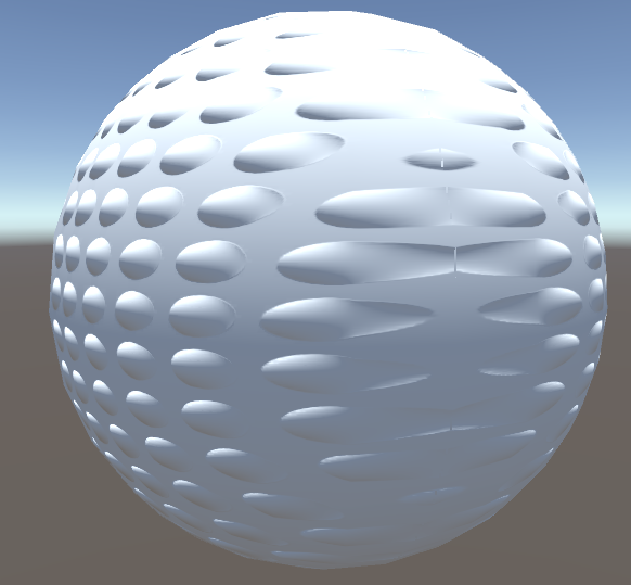
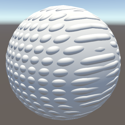
I’ve found a curious artifact of reoriented normal mapping when used on extreme angles. My test case is the normal of a hemisphere with a detail normal of a lot of smaller hemispheres, and where the blended normals are getting pushed to z<0 the cross vector to the normal and z is getting flipped.
Though, I should probably mention my use case was for triplanar mapping, so that first hemisphere normal is actually the world normals of a sphere mesh.
The z clamping proposed back in Sep '13 doesn’t really solve the issue since the normals are already inverted.
Hey Ben,
The method isn’t really designed for object/world normals. In your case, since you’re (triplanar) blending between normal maps, could you not do this in tangent space with PD blending and then transform by the mesh tangent frame after? Or is the goal to blend both base and detail normal maps together?
where the blended normals are getting pushed to z<0 the cross vector to the normal and z is getting flipped.
I’m not sure I 100% follow; there aren’t any cross products in the method, so presumably this is something else that you’re doing afterwards. I’d be happy to take a look at the full thing if you have a minimal Unity demo.
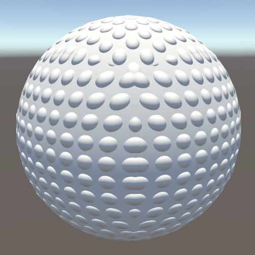
It was my bug. I was blending the normals in the wrong order. As for triplanar mapping, RNM is a perfect use case for it. Similar to how the GPU Gems 3 triplanar mapping is the “UDN” normal map blending with some smart swizzling, you can do the same thing with RNM. I swizzle the vertex normals to match the normal map, apply the blend, then swizzle back.
Ahh, that makes sense. I’m glad to hear that it’s all working now.
Thanks also for posting your results – looking good!